
Which Laser Cutting Defects Can Cause Aerospace Part Rejection?
Aerospace laser-cut parts can be rejected even when the profile appears acceptable to the naked eye. A bracket, shim, duct panel, or thin-gauge structural detail may fit the fixture and still fail acceptance because its cut edge contains a fatigue initiator, an unacceptable thermal alteration, or geometry outside the drawing and process specification. In flight-critical work, the edge is not merely a boundary; it can become part of the load path.
The defects most likely to cause rejection are dross or adherent slag, excessive kerf taper, edge roughness, recast material, microcracking, heat-affected zone damage, dimensional distortion, incomplete cuts, and contamination. The answer to What laser cutting defects affect aerospace part acceptance? is therefore broader than “bad edge quality.” Acceptance depends on whether the defect changes dimensions, material condition, surface integrity, downstream manufacturability, or the part’s ability to meet the applicable inspection criteria.
Why a small cut-edge defect becomes a major aerospace issue
Laser cutting concentrates energy in a narrow zone, which makes it highly effective for complex profiles and thin sheet. The same concentrated heat can create localized conditions that are difficult to judge from the top surface alone. A darkened edge, a thin layer of resolidified metal, or a barely visible crack at a sharp internal feature may become significant after forming, welding, machining, coating, vibration exposure, or cyclic loading.
Rejection is especially likely when the cut edge is part of a hole, slot, notch, lightening feature, mating face, or fastener interface. These features often experience stress concentration or require precise fit. A defect that is tolerable on a noncritical trim edge may be unacceptable at a radius transition, in a high-load attachment area, or where later inspection must confirm an undamaged base material condition.
Inspection personnel generally do not evaluate laser-cut quality by appearance alone. They may assess edge condition, profile accuracy, burr removal, evidence of thermal damage, flatness, and material-specific process requirements. The drawing, purchase requirements, approved manufacturing route, and customer specifications determine the actual acceptance threshold. A visually clean edge does not override those requirements.
Defects that commonly lead to rejection
Dross, slag, and tenacious bottom-edge deposits
Dross forms when molten material is not fully expelled from the kerf and solidifies on the lower edge. It is often associated with unsuitable assist-gas pressure, poor nozzle condition, incorrect focal position, inadequate power-to-speed balance, or contamination on the material surface. On thin sheet, the deposit may look like a minor burr. On thicker material or reactive alloys, it can be hard, irregular, and firmly bonded.
Loose dross may be removable during approved finishing. Tenacious dross is more serious because aggressive removal can alter the edge radius, reduce thickness, create gouges, or erase material needed to maintain dimensional tolerance. It may also interfere with fixture seating, assembly fit, coating coverage, and automated inspection. A part should not be treated as acceptable merely because an operator can “clean it up” without confirming whether such rework is permitted.
Kerf taper and out-of-tolerance cut geometry
A laser kerf is rarely perfectly parallel from top to bottom. Some taper is inherent, but excessive taper changes the effective geometry of slots, holes, tabs, and profiles. A nominally correct opening measured at the top surface may be undersized or oversized at the lower surface. This becomes problematic where a component must accept a fastener, align with a mating part, or maintain a controlled clearance after assembly.
Kerf taper can result from focus position, beam mode, material thickness, lens condition, cutting speed, or an unstable beam path. It should be evaluated in the direction that matters for the feature. For example, a tapered circular hole may affect fastener seating differently than a tapered external profile. Checking only one surface can miss the condition that actually drives rejection.
Roughness, striations, and edge gouging
Vertical striations are a normal visual characteristic of many laser-cut edges, but their depth and consistency matter. Coarse striations, interrupted cut lines, deep gouges, and torn-looking regions can indicate unstable melt ejection or an unsuitable parameter window. Such features can reduce edge quality, complicate coating preparation, and create local stress raisers.
The risk increases near small radii, corners, lead-in and lead-out locations, and regions where machine acceleration changes. A part may show acceptable quality along long straight cuts yet have severe roughness at a small internal contour. Inspection should therefore include geometrically demanding features rather than relying on a general visual impression from an easy-to-cut area.
Recast layer and resolidified material
Recast material is metal that melts during cutting and then resolidifies on the cut surface instead of being fully expelled. Depending on the alloy and process, this layer may differ from the parent material in microstructure, hardness, brittleness, or corrosion behavior. It can also conceal discontinuities beneath an apparently continuous surface.
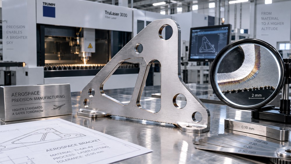
Recast is particularly important for alloys that are sensitive to thermal cycling or for edges that will remain in service without subsequent machining. Where the manufacturing specification limits recast, visual inspection alone may be insufficient. Metallographic examination, process qualification evidence, or other approved verification methods may be necessary when the material condition is uncertain.
Microcracks and heat-affected zone damage
Microcracks are among the most consequential laser cutting defects because they may not be visible without magnification or specialized inspection. They can originate from thermal stress, rapid solidification, excessive energy input, unfavorable chemistry, surface contamination, or a process setting that creates an unstable cut. Corners, narrow webs, pierced areas, and abrupt section changes deserve close attention because heat can accumulate or concentrate there.
The heat-affected zone (HAZ) is not automatically a defect; some thermal influence is expected in thermal cutting. The problem arises when the HAZ exceeds approved limits or produces unacceptable metallurgical changes, discoloration, oxidation, hardness variation, or cracking. In a fatigue-sensitive part, even a localized HAZ issue at a notch or hole can be enough to trigger rejection because the damage may propagate under cyclic loading.
Incomplete penetration, uncut bridges, and irregular breakouts
An incomplete cut may leave a thin uncut ligament, a partial bridge, or a region that separates only when the part is removed from the nest. Forced separation can tear the edge, bend the part, or create a breakout that no longer follows the programmed contour. This often occurs when power drops, focus drifts, the sheet is not flat, assist gas is disrupted, or a previously cut feature affects local heat flow.
Incomplete penetration is not always obvious on the top surface. Inspect the underside, small apertures, and the final portion of long contours. A distorted or torn breakout is more than a cosmetic issue: it can leave an uncontrolled edge condition that cannot be assumed recoverable by deburring.
Oxidation, discoloration, and embedded contamination
Assist-gas selection and shielding behavior affect the chemistry of the cut edge. Oxidation or heavy discoloration can be unacceptable where the material specification limits thermal scale, where corrosion resistance is critical, or where a later bonding, welding, brazing, or coating process requires a controlled surface. Contamination from dirty sheet, degraded protective film, poor gas purity, nozzle contact, or handling can create similar concerns.
Do not assume that a surface treatment will correct every issue. Some coatings can mask discoloration while leaving altered material underneath. If the edge is intended for subsequent joining, the downstream process owner should confirm that the proposed cleaning or finishing route restores the required condition.
A practical way to assess a suspect cut part
When a defect is found, the first task is to separate a removable surface condition from a possible material-integrity issue. The decision should be based on the approved route, not on convenience or appearance. A useful inspection sequence is:
- Verify the affected feature. Identify whether the defect is on a noncritical trim edge, a hole, a slot, a bend line, a mating surface, or a fatigue-sensitive geometry.
- Check the complete edge. Examine top and bottom surfaces, corners, lead-in areas, pierce locations, narrow features, and the reverse side of the sheet.
- Measure before rework. Confirm profile size, hole condition, kerf taper, flatness, and remaining material. Removing dross before measuring can hide the original extent of the issue.
- Compare with process requirements. Review the drawing notes, material controls, approved laser process, edge-break limits, and any requirements for inspection or finishing.
- Decide whether rework is controlled. Light deburring may be allowed, while grinding, blending, polishing, machining, or chemical cleaning may require explicit authorization and reinspection.
- Contain the production lot when needed. A defect caused by focus drift, nozzle wear, gas instability, or parameter error may affect neighboring parts cut under the same conditions.
Apart from direct inspection, production records can help locate the cause. Compare the machine program revision, material heat or batch identification, sheet thickness, nozzle size, lens condition, assist-gas setup, focal setting, and operator-approved parameter set. This is not paperwork for its own sake: it helps determine whether the defect is isolated or systemic.
Process controls that reduce rejection risk
Stable edge quality starts before the laser is fired. Material must be suitable for the qualified process, clean enough for consistent absorption and gas flow, and properly supported to avoid movement or local deflection. Sheet flatness matters because variations in stand-off distance can shift the focal relationship and make a validated program behave differently across the nest.
Consumable condition deserves disciplined attention. A damaged nozzle, contaminated protective window, degraded lens, or poor beam centering can produce defects that appear only in certain directions or at certain positions on the sheet. Periodic verification cuts on representative material can reveal a deteriorating process before production parts accumulate nonconformities.
Programming decisions also matter. Lead-ins should be positioned away from critical functional surfaces where possible. Small holes and narrow slots may require a dedicated cutting strategy rather than the same settings used for large external profiles. Cut order can influence heat buildup and distortion, especially in thin material with closely spaced features. These controls should be established through the approved manufacturing process rather than adjusted casually on the shop floor.
Questions that often arise during acceptance review
Can burrs always be removed and still keep the part acceptable?
No. Removal is acceptable only when the approved requirements allow it and the work does not change dimensions, edge radius, surface condition, or material integrity beyond permitted limits. A burr that is easy to remove may still be associated with excessive dross, taper, or an unstable cutting condition affecting other parts.
Is discoloration alone enough to reject a laser-cut aerospace part?
It can be, depending on the material, location, and specified surface condition. Discoloration may be superficial, but it can also indicate oxidation or thermal exposure that affects later joining, coating, corrosion performance, or required inspection. The correct decision comes from the applicable part and process requirements.
When should a suspected recast layer or microcrack be investigated beyond visual inspection?
Further evaluation is appropriate when the part uses a material sensitive to thermal damage, when the edge serves a fatigue-critical function, when visible evidence suggests overheating or cracking, or when the approved process calls for additional verification. Repeated defects in the same feature or lot should also be treated as a process-control concern rather than a one-part cosmetic issue.